Looking at Fig. 230.1 in the NEC, we can see that the second and third major areas of Art. 230 provide requirements for service entrance conductors (Part IV) and service equipment (Parts V, VI, and VII).
Before you begin a service installation, determine which conductors are actually part of the service (line side of the service equipment) rather than feeders and branch circuits (load side of the service equipment).
Although each service drop or service lateral can supply only one set of service entrance conductors [230.40], there are five exceptions:
Service entrance conductors must have sufficient ampacity for the loads, per Parts III, IV, or V of Art. 220 [230.42].
Before applying any adjustment or correction factors, size the service entrance conductors at least 125% of the continuous loads, plus 100% of the noncontinuous loads. Base your calculations on the terminal temperature rating ampacities listed in Table 310.16 [110.14(C)].
Size the neutral conductor to carry the maximum unbalanced load per 220.61. It also can't be smaller than required by 250.24(C) [230.42(C)].
You can use any of the 16 wiring methods listed in 230.43 for installing service conductors. Follow the applicable Chapter 3 requirements for the wiring method you choose (for example, Art. 358 for EMT). You can also use cable trays, if they contain only service entrance conductors — or if they have a barrier that separates the service conductors from the feeders or branch circuits [230.44].
Splices and taps must comply with 110.14, 300.5(E), 300.13, and 300.15 [230.46].
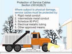
Protect underground conductors from physical damage per 300.5 [230.50(A)]. For all other conductors, install in IMC, RMC, Schedule 80 PVC, or EMT (per Arts. 342, 344, 352, and 358, respectively) or use other means approved by the AHJ (Fig. 1).
Fig. 1. To protect conductors that are not underground from physical damage, follow the guidelines outlined above or consult the AHJ.
Raceways for overhead service drops must have a weatherhead [230.54] — so must service cables. However, you can form SE cable into a gooseneck and tape it with self-sealing weather-resistant thermoplastic. Be sure to support the cables within 1 ft of the weatherhead, raceway connections, or enclosure — and at intervals not exceeding 30 in. [230.51].
Locate service heads and goosenecks above the point of attachment, per 230.26. Where it's impractical to locate the service head above the point of attachment, locate within 2 ft of the point of attachment [230.54(C)].
Service heads must provide a bushed opening, and ungrounded conductors must be in separate openings. Drip loop conductors must be below the service head or below the termination of the service entrance cable sheath. Arrange service drops and service entrance conductors to prevent water from entering service equipment.
The service disconnecting means must consist of either a manually operated switch or a power-operated switch or circuit breaker also capable of being operated manually [230.76]. It must open all service entrance conductors from the premises wiring of the structure [230.70].
A shunt-trip button does not qualify as a service disconnect because it doesn't meet any of the above requirements.
Install the service disconnecting means at a readily accessible location nearest the point of service conductor entry (either inside or outside the structure) [230.70(A)(1)]. In a multiple-occupancy building, each occupant must have access to the service disconnecting means [230.72(C)]. However, if electrical maintenance is provided by continuous building management, the service disconnecting means can be accessible only to building management personnel.
Because service entrance conductors don't have short circuit or ground-fault protection, they must be limited in length when installed inside a building. Some local jurisdictions have specific length requirements (Fig. 2).
Fig. 2. The service disconnecting means must be placed at a readily accessible location nearest the point of service conductor entry.
You can have a maximum of six service disconnects for each service permitted by 230.2, or each set of service entrance conductors permitted by 230.40 Ex 1, 3, 4, or 5 [230.71]. This is per service, not per building. Make sure these are grouped per 230.72.
The service disconnecting means must have an ampere rating of at least the calculated load per Art. 220 [230.79], and the rating of the disconnecting means must be at least:
Don't connect any electrical equipment to the supply side of the service disconnect, except for [230.82]:
Fig. 3. Meter disconnect switches are one of several exceptions to the Code rule that prohibits connecting any electrical equipment to the supply side of the service disconnect.
The NEC doesn't require you to provide short circuit or ground-fault protection for service conductors, but the feeder overcurrent device provides overload protection for the service conductors.
Each ungrounded service conductor must have overload protection at the point where the service conductors terminate [230.90 and 240.21(D)] (Fig. 4).
Fig. 4. Guidelines for overload protection on ungrounded service conductors are found in 230.90 and 240.21(D).
The rating of the overcurrent device must not exceed the ampacity of the conductors. See the five exceptions noted in 230.90(A).
You must provide equipment ground-fault protection for each service disconnecting means rated 1,000A or more, if it's supplied by a 4-wire, 3-phase, 277/480V wye-connected system [230.95]. The rating of the service disconnecting means is considered to be the rating of the largest fuse that can be installed or the highest continuous current trip setting of a circuit breaker.
The NEC prohibits ground-fault protection of equipment for fire pumps [695.6(H)], and doesn't require it for emergency systems [700.26] or legally required standby systems [701.17].
Article 100 defines “Ground-Fault Protection of Equipment” as a system intended to provide protection of equipment from ground faults by opening the overcurrent device at current levels less than those required to protect conductors from damage. This type of protective system is intended to protect connected equipment, not people. See 215.10 for similar requirements for feeders.
To install a service correctly, you must comply with all of Art. 230, and that can seem overwhelming initially. If you first address the conductors and then the equipment, you'll find it easier to get your head around these requirements for any given project.
If you're developing the work breakdown structure (WBS) for a service installation project, refer to Fig. 230.1 in the NEC during that process. This will help you keep your WBS useful, rather than missing a key task or becoming overly detailed.
Service point
The point of connection between the serving utility and the premises wiring.